
This chapter describes the AppleTalk Phase 2 (AP2) configuration commands and includes the following sections:
This section outlines the initial steps required to get the AppleTalk Phase 2 protocol up and running. Information on how to make further configuration changes will be covered in the command sections of this chapter. For the new configuration changes to take effect, the router must be restarted.
When you configure a router to forward AppleTalk Phase 2 packets, you must enable certain parameters regardless of the number or type of interfaces in the router. If you have multiple routers transferring AppleTalk Phase 2 packets, specify these parameters for each router.
| Note: | When enabling AppleTalk over ATM, you must enable the specific emulated LAN interfaces over which AppleTalk is to send packets. You must not enable AppleTalk over the physical ATM interface. All further uses of the word "interface" in this chapter refer to the emulated LAN interface, not the ATM physical interface. |
You must also specify certain parameters for each network and interface that sends and receives AppleTalk Phase 2 packets. After you have specified the parameters, use the AppleTalk Phase 2 list configuration command to view the results of the configuration.
There are two modes for AppleTalk over PPP, full-router and half-router. In full-router mode, the point-to-point network is visible to other AppleTalk routers. In half-router mode, the point-to-point network is invisible to other routers, but it still transmits AppleTalk routing information and data packets.
To set up your network for full-router mode, give each router on the PPP link a common network number, a common zone name, and a unique node number. If you configure one end of the PPP link with a non-zero network number, you must also configure that end to have a non-zero node number and to have a zone name. In this case, the other end of the link must have either:
To set up your network for half-router mode, configure both routers on the PPP link so that network and node numbers are set to zero and no zone name is used.
ZoneName filtering, although not required for AppleTalk, is a very desirable feature for the security and administration of large AppleTalk Internetworks. There are also provisions for restricting access to networks by net numbers.
AppleTalk is structured so that every network is identified in two ways. The first is a network number or range of consecutive network numbers that must be unique throughout the internet. The network number combined with the node number uniquely identifies any end station in the internet.
The second identifier for the network is one or more ZoneNames. These ZoneName strings are not unique throughout the internet. The end station is uniquely identified by a combined object:type:ZoneName-string.
A router first learns about a network when the new net range appears in the RTMP routing update from a neighboring router. The router then queries the neighbor for the ZoneNames of the new network. Note that the net range is repeated in every new RTMP update but that the ZoneNames are requested only once.
The end stations obtain the network numbers from the broadcasted RTMP (routing information) packets and then choose a node number. This net/node pair is then AARP'd for (AARP Probe) to see if any other end station has already claimed its use. If another station responds, another net/node pair is chosen by the end station and the process repeated until no responses are received.
When the typical AppleTalk end station wants to use a service (printer, file server) on the Apple Internet, it first looks at all available Zones and selects one. It then chooses a service type and requests a list of all names advertising the type in the chosen Zone. Several problems arise from this mechanism.
The filtering of network numbers further enhances the security and administration of the internet. Network access is only indirectly controlled by Zone filtering. An unregulated department could add networks with the same Zone names but new net numbers that conflict with other departments. Network number filtering can be used to prevent these random additions of zone names and net numbers from impacting the rest of the network.
The router is configured with an exclusive (meaning block the specified zones) or inclusive (meaning allow only these zones) list of Zones for each direction on each interface. The specified interface will not readvertise filtered Zone information in the defined direction. If all Zones in a network's Zonelist are filtered, network information will also be filtered across the interface.
Use similar commands to create network number filters.
You can use the AP2 CONFIG> list command to display all filter information for the interfaces. In addition, the list command accepts an interface# as an argument so that you can list information for only an interface.
This section covers the steps required to get AP2 up and running. For information on how to make further configuration changes, see "AppleTalk Phase 2 Configuration Commands". For the configuration changes to take effect, you must restart the router.
To access the AP2 configuration environment, enter protocol ap2 at the Config> prompt.
When you configure a router to forward AP2 packets, you must enable certain parameters. If you have multiple routers transferring AP2 packets, specify these parameters for each router. To enable AP2:
AP2 config>enable ap2
AP2 config>enable interface 1
To set up your router as a seed router, you must set the network range, a starting node number, and at least one zone name. You can configure some interfaces on a router as seed routers and leave other interfaces as non-seed routers. You must have at least one seed router for each AppleTalk network, and you should configure several seed routers on a network in case one of them fails.
| Note: | Do not set a network range or a node number for half routers. |
  AP2 config>set net-range
  Interface #  [0]? 1
  First Network range number (1-65279, or 0 to delete) []? 1
  Last Network range number (1-165279) []? 5
Enter the same first and last values for a single-numbered network.
  AP2 config>set node-number
  Interface #  [0]? 1
  Node number (1-253, or 0 to delete) []? 1
  AP2 config>add zone
  Interface # [0]? 1
  Zone name []? Finance
After you have specified the parameters, you can use the list command at the AP2 config> prompt to view your configuration.
Zone filtering lets you filter zones in each direction on each interface. To filter incoming packets, set up an input filter. To filter outgoing packets, set up an output filter. The interface will not readvertise filtered zone information in the direction that you define. Follow these steps to set up a zone filter:
  AP2 config>add zfilter in
  Interface # [0]? 1
  Zone name []? Admin
  AP2 config>enable zfilter in exc
  Interface # [0]? 1
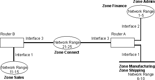
The following are some examples that explain how to set up zone filters in the internet shown in Figure 12.
Figure 12. Example of Zone Filtering

Example 1
The following is an example of how to filter the Manufacturing zone from all other networks. To do this, you would set up an input filter on Interface 1 of Router A to exclude the Manufacturing zone.
  AP2 config>add zfilter in
  Interface # [0]? 1
  Zone name []? Manufacturing
  AP2 config>enable zfilter in exc
  Interface # [0]? 1
This excludes Manufacturing zone information from entering Router A, thereby filtering the zone from the rest of the internet.
Example 2
The following example shows how to filter the Manufacturing zone from Network 11-15, but still allow the Manufacturing zone to be visible on Network 1-5. To do this, you would set up an output filter on Interface 3 of Router A to exclude Manufacturing zone information from being forwarded out of Interface 3. The interface will continue to advertise Manufacturing zone information over interfaces 1 and 2 on Router A, making it visible on Network 1-5.
  AP2 config>add zfilter out
  Interface # [0]? 3
  Zone name []? Manufacturing
  AP2 config>enable zfilter out exc
  Interface # [0]? 3
This filter excludes Manufacturing zone information from the output of Interface 3.
Example 3
The next example shows how to set up a filter so that the Admin zone is visible on all networks, but the Finance zone is not visible to the rest of the internet.
  AP2 config>add zfilter in
  Interface # [0]? 2
  Zone name []? Admin
  AP2 config>enable zfilter in inc
  Interface # [0]? 2
By setting up this input filter as inclusive, only Admin zone information is forwarded through Interface 2 to the rest of the internet.
Network filters are similar to zone filters, except they let you filter an entire network. To set up a network filter:
  AP2 config>add nfilter out
  Interface # [0]? 2
  First Network range number (decimal) [0]? 11
  Last Network range number (decimal) [0]? 15
The network range you enter here must match the range that you assigned to that network.
  AP2 config>enable nfilter in exc
  Interface # [0]? 2
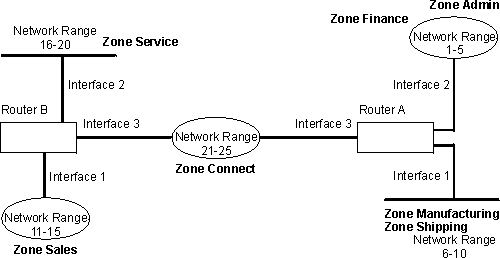
Following are some examples that explain how to set up network filters in the internet, as shown in Figure 13.
Figure 13. Example of Network Filtering

The following steps show how to filter Network 6-10 so that it is not visible to Network 16-20 as shown in Figure 13.
  AP2 config>add nfilter out
  Interface # [0]? 2
  First Network range number (decimal) [0]? 6
  Last Network range number (decimal) [0]? 10
  AP2 config>enable nfilter out exc
  Interface # [0]? 2
This filter excludes all information on Network 6-10 from being forwarded through Interface 2 to Network 16-20.